Thursday, August 18, 2011

Gail India Ltd. Special Recruitment Drive for SC/ST/OBC


Gail (India) Limited
(A Govt. of India Undertaking)
Special Recruitment Drive for SC/ST/OBC (Non-Creamy Layer)

GAIL (India) Limited invites applications under Special Recruitment Drive to fill the following posts in various diciplines for Sheduled Castes / Sheduled Tribes and Other Backward Classes.
    1. Senior Engineer : 11 Posts
    • Grade : E2
    • Disciplines : Telemetry - 02 , Mechanical - 03, Electrical - 05 , Chemical - 01
    2. Senior Officer : 09 Posts
    • Grade : E2
    • Disciplines : Marketing - 06 , Law - 01, HR - 01 , F & A - 01
    3. Deputy Manager : 07 Posts
    • Grade : E3
    • Disciplines : HR - 03 , F & A - 04
    4. Senior Manager (Fire & Safety ) : 03 Posts
    • Grade : E5
Last Date for online Apply : 2400 Hrs on 10.09.2011
Online Apply Starts : 23.08.2011

    For Detailed Advertisement , eligibilty requirements , instructions and for filling the online application form , please visit GAIL .

More Detail will be available at Vacancy Detail

Indian Ordnance Factories Recruitment

Indian Ordnance Factory (Ministry of Defence) invites applications for the recruitment of Machinist, Welder and Electrician vacancies in Indian Ordnance Factory West Bengal.

1. Machinist: 165 posts
2. Welder: 06 posts
3. Electrician: 04 posts

Age limit: The candidate’s age limit is 18 to 32 years, reservation as per rules.
Educational qualification: Candidates passed Matriculation or equivalent examination, must possess National Council for Vocational Training (NCTVT) certificate in the relevant trade failing which ITI or equivalent Diploma/certificate holder in the respective trade.

Application fee: Candidates pay the fee in the form of Crossed Indian Postal Order (IPO) or Bank draft of Rs 50/- (No fee for SC/ST/EXSM/PWD candidates) drawn in favour of The General Manager, Gun & Shell Factory, payable at Kolkata.

Last date for receipt of application: 08-09-2011

For more details Click here

Wednesday, August 17, 2011

Bureau of Indian Standards Scientist - B Recruitment

Bureau of Indian Standards
Manak Bhawan, 9 Bahadur Shah Zafar Marg, New Delhi-110002

Bureau of Indian Standards (BIS), a statutory body under the administrative control of Ministry of Consumer Affairs, Food & Public Distribution, Govt. of India invites online applications for recruitment to 115 post of SCIENTIST-B
    1. Scientist B : 115 Posts
    • Pay Scale : Rs. 15600-39100+Grade Pay Rs.5400 plus allowances
    • Disciplines :
        Mechanical /Metallurgy - 61 Civil - 22 Food/ Microbiology/ Bio Chemistry - 17 Electrical/Electronics - 12 Computer Science/Computer Engg. -03
    • Age Limit : 21-27 years of age as on 09.09.2011 (Relaxable as per rules)

Qualification : For Mechanical / Metallurgy / Civil / Electrical / Electronics / Food/Computer : Bachelor’s Degree in Engineering or Technology or equivalent with 60% marks (55% for SC/ST . For other Disciplines : Master’s Degree in Natural Sciences or equivalent with 60% marks (55% for SC/ST)

Last Date for Online Apply : 09.09.2011
Opening Date for On-Line Registration of Application : 20.08.2011

    Candidates are required to apply OnLine through BIS website

For Further Detail, Application Form, Please Visit http://bis.org.in/other/DetailedAdvertisement2011.pdf

Hindustan Aeronautics Limited Recruitment


Hindustan Aeronautics Limited
Koraput Division

Applications are invited from eligiblie candidates in the prescribed format for the following posts in Hindustan Aeronautics Limited
    1. Assistant Engineers (Mechanical / Production / Metallurgy / Electrical / Electronics / Civil / Computers) : 36 Posts , Scale : Rs. 12600-3%-32500
    2. Assistant Medical Officer : 05 Posts , Pay Scale : Rs. 12600-3%-32500/-
    3. Security Officer (on Contract) : 01 Post , Pay Scale : Rs. 16400-3%-40500/-
    4. Fire Officer : 01 Post , Pay Scale : Rs. 16400-3%-40500/-
    5. Senior Medical Officer : 02 Posts (Anaesthesia - 01, Paediatricsm - 01 ) , Pay Scale : Rs. 20600-46500/-
Last Date for online apply : 24.09.2011
Online Apply Starts : 05.09.2011


    Details of age , qualification , experience , job specification and other details will be available at the wesite .

For More Detail Please visit http://www.hal-india.com/careersnew.asp

Monday, August 15, 2011

VSSC Graduate & Technician Apprentice Recruitmemt


Government of India
Department of Space
Vikram Sarabhai Space Centre
Thiruvananthapuram-695022
Advertisement No. VSSC-265
Requires Graduate & Technician Apprentices

Applications are invited for the following posts of Graduate and Technician Apprentices under the Apprentices Act 1961
    1. Graduate Apprentice : 109 Posts
    • Qualification :B.Tech / BE Degree with Ist class (min. 65%) from a recognised university.
    • Disciplines :
        Aeronautical Engg. - 06 Chemical Engg. - 05 Civil Engg. - 04 Computer Sci. / Engg. - 08 Electrical Engg. -04 Electonics Engg. - 30 Mechanical Engg. - 29 Metallurgy Engg. - 04 Production Engg. - 05 Library Science - 14
    • Stipend : Rs. 5000/-
    2. Technician Apprentice : 166 Posts
    • Qualification : Ist class Diploma in Engineering / Technology from a State Council / Board of Technical Education.
    • Disciplines :
        Aeronautical Engg. - 08 Chemical Engg. - 25 Civil Engg. - 08 Computer Sci. / Engg. - 15 Electrical Engg. -10 Electonics Engg. - 40 Instument Technology - 06 Mechanical Engg. - 46 Catering Technology - 08
    • Stipend : Rs. 3000/-
Last Date for Online Apply : 02.09.2011
Online Registration Starts : 17.08.2011

    Interested candidates may apply online through the website www.vssc.gov.in . Applications will be received by online only. Acknoldgement of the web application affixing recent passport sizre photograph and attestd copies of all certificates may be sent to The Administative Officer , Recruitment & Review Division , , VSSC , ISRO Post , Thiruvananthapuram - 695022

For Further Detail and Online Apply, Please visit http://www.vssc.gov.in/internet/getPage.php?page=Recruitment%20Home&pageId=290

Wednesday, August 10, 2011

CONVENTIONAL SIGNS


Scales


The selection of scale is one of the most important considerations during mapping. It is decided on the basis of :
•  purpose of the map;
•  nature of terrain to be mapped;
•  the size of the final sheet;
•  availability of resources to get it prepared and printed.
Some of these factors are of opposite and conflicting in nature.Therefore, in selecting the scale, the map-maker has to make a judicious decision and to make a compromise.
Table - Suggested scales for different types of survey
Serial No
Purpose of Survey
Scale
R.F.
1.
Land Survey
1 cm = 5 m to 50 m
1:500 to 1:5000
2.
Topographical Survey
1 cm = 0.25 km to 2.5 km
1:25,000 to 1:250,000
3.
Building Site
1 cm = 10 m
1:1000
4.
Route Survey
1 cm = 100 m
1:10,000
5.
Town Planning
1 cm = 100 m
1:10,000

Engineering drawing

An engineering drawing is a tool that used to communicate the design and manufacturing information for a part. Important elements of an engineering drawing are the dimensions and tolerances. The graphical representation of an object is also called drawing.
“An engineering drawing is a document that communicates a precise description of a part. This description consists of pictures, words, numbers and symbols.” Together, these elements communicate part information to all drawing users.

Engineering drawing information includes;

1. Geometry (Shape, size and form of the part)
2. Critical functional relationships.
3. Tolerances allowed for proper function.
4. Material, heat treat, surface coatings.
5. Part documentation information (Part Name, Part Number, Revision level).

Standard Drawing Sheets Sizes:

Orthographic Projection

If straight lines are drawn from the various points on the contour of an object to meet a plane, the object is said to be “projected on the plane”.The figure formed by joining in correct sequence, the points at which these lines meet the plane is called a “projection of the object”.The straight lines which are passed through an object and projected on the plane are called “projection”. orA projection is defined as a view imagined to be projected on to a plane known as the projection plane. While projecting, if the “rays of sight” (projectors)Are taken perpendicular to the plane of projection. The projection method is then called orthographic projection. In this method the observer is assumed to be at definite distance from the plane of projection, such that the projectors will be parallel to each other.

Orthographic Views:
Orthographic views consists of one, two or more separate views of an object taken from different directions, generally at right angles to each other and arranged in  a different manner. These views collectively describe the object.Orthographic views of any object can be represented by any one the two systems of projections.
The First angle projection and The Third angle projection. These are named according to the quadrant in which the object is imagined to be placed for purposes of projection. As far as the shape and size of the views are concerned there is no difference between these two.

First Angle Projection & Third Angle Projection:

Engineering Drawing

Introduction

One of the best ways to communicate one's ideas is through some form of picture or drawing. This is especially true for the engineer. The purpose of this guide is to give you the basics of engineering sketching and drawing.
We will treat "sketching" and "drawing" as one. "Sketching" generally means freehand drawing. "Drawing" usually means using drawing instruments, from compasses to computers to bring precision to the drawings.
This is just an introduction. Don't worry about understanding every detail right now - just get a general feel for the language of graphics.
We hope you like the object in Figure 1, because you'll be seeing a lot of it. Before we get started on any technical drawings, let's get a good look at this strange block from several angles.
Figure 1 - A Machined Block
 

Isometric Drawing

The representation of the object in figure 2 is called an isometric drawing. This is one of a family of three-dimensional views called pictorial drawings. In an isometric drawing, the object's vertical lines are drawn vertically, and the horizontal lines in the width and depth planes are shown at 30 degrees to the horizontal. When drawn under these guidelines, the lines parallel to these three axes are at their true (scale) lengths. Lines that are not parallel to these axes will not be of their true length.
Figure 2 - An Isometric Drawing
 
Any engineering drawing should show everything: a complete understanding of the object should be possible from the drawing. If the isometric drawing can show all details and all dimensions on one drawing, it is ideal. One can pack a great deal of information into an isometric drawing. However, if the object in figure 2 had a hole on the back side, it would not be visible using a single isometric drawing. In order to get a more complete view of the object, an orthographic projection may be used.

Orthographic or Multiview Drawing

Imagine that you have an object suspended by transparent threads inside a glass box, as in figure 3.
Figure 3 - The block suspended in a glass box
 
Then draw the object on each of three faces as seen from that direction. Unfold the box (figure 4) and you have the three views. We call this an "orthographic" or "multiview" drawing.
Figure 4 - The creation of an orthographic multiview drawing
 
Figure 5 shows how the three views appear on a piece of paper after unfolding the box.
Figure 5 - A multiview drawing and its explanation
 
Which views should one choose for a multiview drawing? The views that reveal every detail about the object. Three views are not always necessary; we need only as many views as are required to describe the object fully. For example, some objects need only two views, while others need four. The circular object in figure 6 requires only two views.
Figure 6 - An object needing only two orthogonal views
 

Dimensioning

Figure 7 - An isometric view with dimensions
 
We have "dimensioned" the object in the isometric drawing in figure 7. As a general guideline to dimensioning, try to think that you would make an object and dimension it in the most useful way. Put in exactly as many dimensions as are necessary for the craftsperson to make it -no more, no less. Do not put in redundant dimensions. Not only will these clutter the drawing, but if "tolerances" or accuracy levels have been included, the redundant dimensions often lead to conflicts when the tolerance allowances can be added in different ways.
Repeatedly measuring from one point to another will lead to inaccuracies. It is often better to measure from one end to various points. This gives the dimensions a reference standard. It is helpful to choose the placement of the dimension in the order in which a machinist would create the part. This convention may take some experience.

Sectioning

There are many times when the interior details of an object cannot be seen from the outside (figure 8).
Figure 8 - An isometric drawing that does not show all details
 
We can get around this by pretending to cut the object on a plane and showing the "sectional view". The sectional view is applicable to objects like engine blocks, where the interior details are intricate and would be very difficult to understand through the use of "hidden" lines (hidden lines are, by convention, dotted) on an orthographic or isometric drawing.
Imagine slicing the object in the middle (figure 9):
Figure 9 - "Sectioning" an object
 
Figure 10 - Sectioning the object in figure 8
 
Take away the front half (figure 10) and what you have is a full section view (figure 11).
Figure 11 - Sectioned isometric and orthogonal views
 
The cross-section looks like figure 11 when it is viewed from straight ahead.

Drawing Tools

To prepare a drawing, one can use manual drafting instruments (figure 12) or computer-aided drafting or design, or CAD. The basic drawing standards and conventions are the same regardless of what design tool you use to make the drawings. In learning drafting, we will approach it from the perspective of manual drafting. If the drawing is made without either instruments or CAD, it is called a freehand sketch.
Figure 12 - Drawing Tools
 

"Assembly" Drawings

An isometric view of an "assembled" pillow-block bearing system is shown in figure 13. It corresponds closely to what you actually see when viewing the object from a particular angle. We cannot tell what the inside of the part looks like from this view.
We can also show isometric views of the pillow-block being taken apart or "disassembled" (figure 14). This allows you to see the inner components of the bearing system. Isometric drawings can show overall arrangement clearly, but not the details and the dimensions.
Figure 13 - Pillow-block (Freehand sketch)
 
Figure 14 - Disassembled Pillow-block
 

Cross-Sectional Views

A cross-sectional view portrays a cut-away portion of the object and is another way to show hidden components in a device.
Imagine a plane that cuts vertically through the center of the pillow block as shown in figure 15. Then imagine removing the material from the front of this plane, as shown in figure 16.
Figure 15 - Pillow Block Figure 16 - Pillow Block
 
This is how the remaining rear section would look. Diagonal lines (cross-hatches) show regions where materials have been cut by the cutting plane.
Figure 17 - Section "A-A"
 
This cross-sectional view (section A-A, figure 17), one that is orthogonal to the viewing direction, shows the relationships of lengths and diameters better. These drawings are easier to make than isometric drawings. Seasoned engineers can interpret orthogonal drawings without needing an isometric drawing, but this takes a bit of practice.
The top "outside" view of the bearing is shown in figure 18. It is an orthogonal (perpendicular) projection. Notice the direction of the arrows for the "A-A" cutting plane.
Figure 18 - The top "outside" view of the bearing
 

Half-Sections

A half-section is a view of an object showing one-half of the view in section, as in figure 19 and 20.
Figure 19 - Full and sectioned isometric views

Figure 20 - Front view and half section

The diagonal lines on the section drawing are used to indicate the area that has been theoretically cut. These lines are called section lining or cross-hatching. The lines are thin and are usually drawn at a 45-degree angle to the major outline of the object. The spacing between lines should be uniform.
A second, rarer, use of cross-hatching is to indicate the material of the object. One form of cross-hatching may be used for cast iron, another for bronze, and so forth. More usually, the type of material is indicated elsewhere on the drawing, making the use of different types of cross-hatching unnecessary.
Figure 21 - Half section without hidden lines
 
Usually hidden (dotted) lines are not used on the cross-section unless they are needed for dimensioning purposes. Also, some hidden lines on the non-sectioned part of the drawings are not needed (figure 12) since they become redundant information and may clutter the drawing.

Sectioning Objects with Holes, Ribs, Etc.

The cross-section on the right of figure 22 is technically correct. However, the convention in a drawing is to show the view on the left as the preferred method for sectioning this type of object.
Figure 22 - Cross section
 

Dimensioning

The purpose of dimensioning is to provide a clear and complete description of an object. A complete set of dimensions will permit only one interpretation needed to construct the part. Dimensioning should follow these guidelines.
  1. Accuracy: correct values must be given.
  2. Clearness: dimensions must be placed in appropriate positions.
  3. Completeness: nothing must be left out, and nothing duplicated.
  4. Readability: the appropriate line quality must be used for legibility.

The Basics: Definitions and Dimensions

The dimension line is a thin line, broken in the middle to allow the placement of the dimension value, with arrowheads at each end (figure 23).
Figure 23 - Dimensioned Drawing
 
An arrowhead is approximately 3 mm long and 1 mm wide. That is, the length is roughly three times the width. An extension line extends a line on the object to the dimension line. The first dimension line should be approximately 12 mm (0.6 in) from the object. Extension lines begin 1.5 mm from the object and extend 3 mm from the last dimension line.
A leader is a thin line used to connect a dimension with a particular area (figure 24).
Figure 24 - Example drawing with a leader
 
A leader may also be used to indicate a note or comment about a specific area. When there is limited space, a heavy black dot may be substituted for the arrows, as in figure 23. Also in this drawing, two holes are identical, allowing the "2x" notation to be used and the dimension to point to only one of the circles.

Where To Put Dimensions

The dimensions should be placed on the face that describes the feature most clearly. Examples of appropriate and inappropriate placing of dimensions are shown in figure 25.
Figure 25 - Example of appropriate and inappropriate dimensioning
 
In order to get the feel of what dimensioning is all about, we can start with a simple rectangular block. With this simple object, only three dimensions are needed to describe it completely (figure 26). There is little choice on where to put its dimensions.
Figure 26 - Simple Object
 
We have to make some choices when we dimension a block with a notch or cutout (figure 27). It is usually best to dimension from a common line or surface. This can be called the datum line of surface. This eliminates the addition of measurement or machining inaccuracies that would come from "chain" or "series" dimensioning. Notice how the dimensions originate on the datum surfaces. We chose one datum surface in figure 27, and another in figure 28. As long as we are consistent, it makes no difference. (We are just showing the top view).
Figure 27 - Surface datum example
 
Figure 28 - Surface datum example
 
In figure 29 we have shown a hole that we have chosen to dimension on the left side of the object. The Ø stands for "diameter".
Figure 29 - Exampled of a dimensioned hole

When the left side of the block is "radiuses" as in figure 30, we break our rule that we should not duplicate dimensions. The total length is known because the radius of the curve on the left side is given. Then, for clarity, we add the overall length of 60 and we note that it is a reference (REF) dimension. This means that it is not really required.
Figure 30 - Example of a directly dimensioned hole
 
Somewhere on the paper, usually the bottom, there should be placed information on what measuring system is being used (e.g. inches and millimeters) and also the scale of the drawing.
Figure 31 - Example of a directly dimensioned hole

This drawing is symmetric about the horizontal centerline. Centerlines (chain-dotted) are used for symmetric objects, and also for the center of circles and holes. We can dimension directly to the centerline, as in figure 31. In some cases this method can be clearer than just dimensioning between surfaces.

Tuesday, August 9, 2011

UPSC Junior Works Manager Mechanical Engineering Solved Paper


Exam Held On: 09-01-2011                                                           

PSU Selection Procedure


The usual selection procedure followed by maximum no. of PSU’s:
STAGE I:- Written Examination (Generally on Sunday)
STAGEII:- Interview & GD
STAGE III:- Medical Examination
NOTE:
a) Apart from these, there can be an additional stage in some of the PSUs where only short-listed candidates are allowed to appear for the written exam. All the applicants fulfilling the eligibility criteria are screened again on the basis of their % of B.Tech primarily and depending upon the no. of vacancies Only selected candidates are called for the written exam. eg- ISRO, BHEL etc.

b) Some PSUs don’t hold interviewer as a part of their selection procedure eg- BSNL(JTO).

c) Though it has not ever been declared by any PSU, the general trend seen in according weightage to different stages in the final selection is:-
Written – 70-85%
Interview – 15-30%
GD – 5%

STAGE-I :- Written Examination.
Duration:- 1–3 hr (Avg 2 hour)

Written exam of various PSUs can be divided mainly into 4 sections:-
i) Technical
ii) Aptitude & Reasoning
iii) English & RC
iv) General Awareness & current affairs
1) Technical:- 60 – 120 questions (exact no. varies for diff PSUs)
Average no of Questions -80
Depending on the level of Technical Questions PSUs can be categorized as

Level-I:- Tough
eg – DRDO, ISRO etc.

Level-II:- Moderate
eg – BHEL, HAL, ONGC, SALL, JTO, NTPC etc.

Level-III:- Easy
eg – AAI etc.

ii) Aptitude & Reasoning:- Quantitative Reasoning (Speed-distance, percentage, profit- loss etc), Maths of 10th std level,Figure based Questions etc. iii) English & RC:- Reading Comprehension, Questions based on Vocabulary and English grammar etc.

iv) General Awareness & Current Affairs:-
(1) Current affairs and questions based on general knowledge
(2)Some PSUs ask specific questions related to their institutions in this section eg:- DRDO asks about its labs in India (1 or 2 questions).

NOTE:- The 4th section may on may not be present. Generally, 1st through 3rd sections are present in most of the exams.

Stage – II Interview:
1) Maximum stress on testing the technical knowledge of the Candidate.
2) % of HR Question limited to the general introduction, work experience (if any), hobbies etc.
3) Final year project is very important for the interview.

GD:

(1) duration is 20 -30 minutes .
(2) Usually easy topics are given for discussion.
(3) Contemporary social and political issues are highly probable topics to be given.
(4) topics on environmental and technical issues can also be given.
NOTE:- Interview & GD in most of the PSU’s can also be taken in Hindi.

Stage-III Medical Examination :

Candidates selected on the basis of their performance in written exam, interview and GD are finally called for a medical check-up prior to their  appointment and training.

Monday, August 8, 2011

DRDO 2009 QUESTION PAPER


Sunday, August 7, 2011

VIZAG STEEL MANAGEMENT TRAINEE MECHANICAL QUESTION PAPER 2011


VIZAG STEEL MANAGEMENT TRAINEE ELECTRICAL QUESTION PAPER


IES 2011 CIVIL ENGINEERING PAPER - 1


IES 2011 CIVIL ENGINEERING PAPER - 2


IES 2011 ELECTRICAL PAPER - 1


IES 2011 ELECTRICAL PAPER - 2


IES 2011 ELECTRONICS PAPER - 1


IES 2011 ELECTRONICS PAPER - 2


IES 2011 MECHANICAL PAPER - 1


IES 2011 MECHANICAL PAPER - 2

GATE question papers (EC) 2010

GATE question papers Electronics and Communication Engineering 2010 (EC)

                                               
                                                Q. No. 1 – 25 Carry One Mark Each

1.         The eigen values of a skew-symmetric matrix are
            (A)        always zero                                           (B)        always pure imaginary
            (C)        either zero or pure imaginary                  (D)        always real

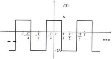
2.         The trigonometric Fourier series for the waveform f(t) shown below contains


            (A)        only cosine terms and zero value for the dc component
            (B)        only cosine terms and a positive value for the dc component
            (C)        only cosine terms and a negative value for the dc component
            (D)        only sine terms and a negative for the dc component

3.         A function n(x) satisfied the differential equation  where L is a constant. The boundary conditions are: n(0)=K and n ( ∞ ) = 0. The solution to this equation is
            (A)        n(x) = K exp(x/L)                                    (B)        n(x) = K exp(-x/ )
            (C)        n(x) = K2 exp(-x/L)                                 (D)        n(x) = K exp(-x/L)

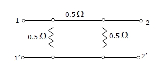
4.         For the two-port network shown below, the short-circuit admittance parameter matrix is


            (A)             (B)                    (C)            (D)       

5.         For parallel RLC circuit, which one of the following statements is NOT correct?
            (A)        The bandwidth of the circuit deceases if R is increased
            (B)        The bandwidth of the circuit remains same if L is increased
            (C)        At resonance, input impedance is a real quantity
            (D)        At resonance, the magnitude of input impedance attains its minimum value.

6.         At room temperature, a possible value for the mobility of electrons in the inversion layer of a silicon n-channel MOSFET is
            (A)        450 cm2/V-s       (B)        1350 cm2/V-s      (C)        1800 cm2/V-s      (D)        3600 cm2/V-s

7.         Thin gate oxide in a CMOS process in preferably grown using
            (A)        wet oxidation                                         (B)        dry oxidation
            (C)        epitaxial deposition                                 (D)        ion implantation

8.         In the silicon BJT circuit shown below, assume that the emitter area of transistor Q1 is half that of transistor Q2.


            The value of current I0 is approximately
            (A)        0.5 mA              (B)        2mA                  (C)        9.3 mA              (D)        15mA

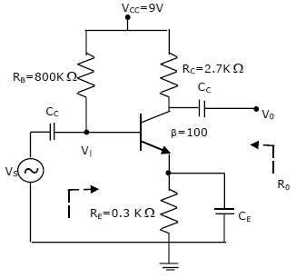
9.         The amplifier circuit shown below uses a silicon transistor. The capacitors CC and CE can be assumed to be short at signal frequency and the effect of output resistance r0 can be ignored. If CE is disconnected from the circuit, which one of the following statements is TRUE?
                                   
                                   
            (A)        The input resistance Ri increases and the magnitude of voltage gain AV decreases
            (B)        The input resistance Ri decreases and the magnitude of voltage gain AV decreases
            (C)        Both input resistance Ri and the magnitude of voltage gain AV decrease
            (D)        Both input resistance Ri and the magnitude of voltage gain AV increase

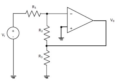
10.        Assuming the OP-AMP to be ideal, the voltage gain of the amplifier shown below is
                                   
            (A)                                                           (B)                      
            (C)                                                      (D)        -

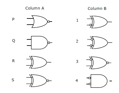
11.        Match the logic ga5tes in Column A with their equivalents in Column B.
   
            (A)        P–2, Q-4, R-1, S-3                                  (B)        P-4, Q-2, R-1, S-3
            (C)        P–2, Q-4, R-3, S-1                                  (D)        P-4, Q-2, R-3, S-1

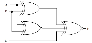
12.        For the output F to be 1 in the logic circuit shown, the input combination should be


            (A)        A = 1, B= 1. C = 0                                 (B)        A = 1, B= 0,C = 0
            (C)        A = 0, B= 1. C = 0                                 (D)        A = 0, B= 0, C = 1

13.        In the circuit shown, the device connected to Y5 can have address in the range


            (A)        2000 - 20FF       (B)        2D00 – 2DFF      (C)        2E00 – 2EFF      (D)        FD00 - FDFF

14.        Consider the z-transform X(z) = 5z2 + 4z-1 + 3; 0<|z| < ∞ . The inverse z transform x[n] is
            (A)        5d[n + 2] + 3d [n] + 4d [n – 1]                 (B)        5d [n - 2] + 3d [n] + 4d [n + 1]
            (C)        5 u[n + 2] + 3 u[n] + 4 u[n – 1]   (D)        5 u[n - 2] + 3 u[n] + 4 u[n + 1]

15.        Two discrete time systems with impulse responses h1[n] = d [n -1] and h2[n] = d [n – 2] are connected in cascade. The overall impulse response of the cascaded system is
            (A)        d [n - 1] + d [n - 2]                                 (B)        d [n - 4]
            (C)        d [n - 3]                                                 (D)        d [n - 1] d [n - 2]

16.        For an N-point FFT algorithm with N = 2m which one of the following statements is TRUE?
            (A)        It is not possible to construct a signal flow graph with both input and output in normal order
            (B)        The number of butterflies in the mth stage is N/m
            (C)        In-place computation requires storage of only 2N node data
            (D)        Computation of a butterfly requires only one complex multiplication

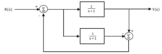
17.        The transfer function Y(s)/R(s) of the system shown is


            (A)        0                      (B)                        (C)                       (D)       

18.        A system with transfer function  has an output y(t) = cos  for the input signal x(t) = p cos. Then, the system parameter ‘p’ is
            (A)                         (B)                          (C)        1                      (D)       

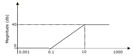
19.        For the asymptotic Bode magnitude plot shown below, the system transfer function can be


            (A)                   (B)                  (C)                                (D)       

20.        Suppose that the modulating signal is m(t) = 2cos (2p fmt) and the carrier signal is xC(t) = AC cos(2pfct), which one of the following is a conventional AM signal without over-modulation?
            (A)        x(t) = Acm(t) cos(2pfct)                          
            (B)        x(t) = Ac[1 + m(t)]cos(2pfct)
            (C)        x(t) = Ac cos(2pfct) + m(t) cos(2pfct)
            (D)        x(t) = Ac cos(2pfmt) cos(2pfct) + Ac sin(2pfmt) sin(2pfct)

21.        Consider an angle modulated signal x(t) = 6cos[2px106t+2sin(8000pt) + 4cos(8000pt)] V. The average power of x(t) is.
            (A)        10W                  (B)        18W                  (C)        20W                  (D)        28W

22.        If the scattering matrix [S] of a two port network is[S] = then the network is
            (A)        lossless and reciprocal                            (B)        lossless but not reciprocal
            (C)        not lossless but reciprocal                       (D)        neither lossless nor reciprocal

23.        A transmission line has a characteristic impedance of 50 Ω and a resistance of 0.1 Ω /m. if the line is distortion less, the attenuation constant (in Np/m) is
            (A)        500                   (B)        5                      (C)        0.014                (D)        0.002

24.        Consider the pulse shape s(t) as shown. The impulse response h(t) of the filter matched to this pulse is
      
25.        The electric field component of a time harmonic plane EM wave traveling in a nonmagnetic lossless dielectric medium has an amplitude of 1 V/m. If the relative permittivity of the medium is 4, the magnitude of the time-average power density vector (in W/m2) is
            (A)                         (B)                        (C)                      (D)      

Q. No. 26 – 51 Carry Two Marks Each

26.        If ey = then y has a
            (A)        maximum at x= e                                   (B)        minimum at x= e
            (C)        maximum at x= e-1                                 (D)        minimum at x= e-1

27.        A fair coin is tossed independently four times. The probability of the event “the number of time heads shown up is more than the number of times tails shown up” is
            (A)                           (B)                           (C)                           (D)      

28.        If  = xy  + x2 then over the path shown in the figure is
            (A)        0                      (B)                          (C)        1          (D)        2

29.        The residues of a complex function X(z) =  at its poles are
            (A)        and 1                                         (B)        and -1
            (C)        , -1 and -                                      (D)        , -1 and    

30.        Consider differential equation with the initial condition y(0) = 0. Using Euler’s first order method with a step size of 0.1, the value of y (0.3) is
            (A)        0.01                  (B)        0.031                (C)        0.0631              (D)        0.1


31.        Given f(t) = L-1, then the value of K is
            (A)        1                      (B)        2                      (C)        3                      (D)        4


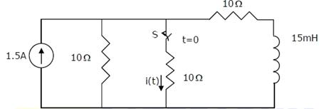
32.        In the circuit shown, the switch S is open for a long time and is closed at t=0. The current i(t) for t≥0+ is

            (A)        i(t)=0.5-0.125e-1000t A                            (B)        i(t)=1.5-0.125e-1000t A
            (C)        i(t)=0.5-0.5e-1000t A                                (D)        i(t)=0.375e-1000t A

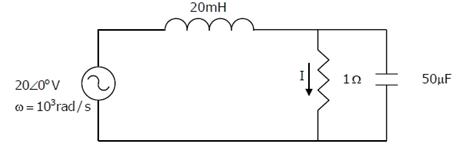
33.        The current I in the circuit shown is
            (A)        -j1A                  (B)        J1A                   (C)        0A                    (D)        20A

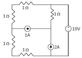
34.        In the circuit shown, the power supplied by the voltage source is
            (A)        0W                   (B)        5W                   (C)        10W                  (D)        100W

35.        In a uniformly doped BJT, assume that NE, NB and NC are the emitter, base and collector dopings in atoms/cm3, respectively. If the emitter injection efficiency of the BJT is close unity, which one of the following conditions is TRUE?
            (A)        NE=NB=NC                                              (B)        NE >>NB and NB>NC
            (C)        NE=NB and NBC                                    (D)        NEBC

36.        Compared to a p-n junction with NA=ND=1014/cm3, which one of the following statements is TRUE for a p-n junction with NA=ND=1020/cm3?
            (A)        Reverse breakdown voltage is lower and depletion capacitance is lower
            (B)        Reverse breakdown voltage is higher and depletion capacitance is lower
            (C)        Reverse breakdown voltage is lower and depletion capacitance is higher
            (D)        Reverse breakdown voltage is higher and depletion capacitance is higher

37.        Assuming that flip-flops are in reset condition initially, the count sequence observed at QA in the circuit shown is

            (A)        0010111…         (B)        0001011…         (C)        0101111…         (D)        0110100…

38.        The transfer characteristic for the precision rectifier circuit shown below is (assume ideal OP-AMP and practical diodes)

39.        The Boolean function realized by the logic circuit shown is


            (A)        F= Σm(0,1,3,5,9,10,14)                          (B)        F= Σm(2,3,5,7,8,12,13)
            (C)        F= Σm(1,2,4,5,11,14,15)                         (D)        F= Σm(2,3,5,7,8,9,12)

40.        For the 8085 assembly language program given below, the content of the accumulator after the execution of the program is
           
3000
MVI
A,
45H
3002
MOV
B,
A
3003
STC


3004
CMC


3005
RAR


3006
XRA
B


            (A)        00H                   (B)        45H                   (C)        67H                   (D)        E7H

41.        A continuous time LTI system is described by
           
            Assuming zero initial conditions, the response y(t) of the above system for the input x(t)=e-2t u(t) is given by
            (A)        (et-e3t)u(t)                                             (B)        (e-t-3-3t)u(t)
            (C)        (e-t+e-3t)u(t)                                          (D)        (et+e3t)u(t)

42.        The transfer function of a discrete time LTI system is given by
           

            Consider the following statements:
            S1: The system is stable and causal for ROC:|z|>½
            S2: The system is stable but not causal for ROC:|z|<¼
            S3: The system is neither stable nor causal for ROC: ¼<|z|<½
            Which one of the following statements is valid?
            (A)        Both S1 and S2 are true              (B)        Both S2 and S3 are true
            (C)        Both S1 and S3 are true              (D)        S1, S2 and S3 are all true

43.        The Nyquist sampling rate for the signal s(t) = is given by
            (A)        400 Hz              (B)        600 Hz              (C)        1200Hz (D)        1400 Hz
44.        A unity negative feedback closed loop system has a plant with the transfer function and a controller Gc(S) in the feed forward path. For a unit set input, the transfer function of the controller that gives minimum steady state error is
            (A)                                              (B)       
            (C)                                   (D)       

45.        X(t) is a stationary process with the power spectral density Sx(f)>0 for all f. The process is passed through a system shown below.


            Let Sy(f) be the power spectral density of Y(t). Which one of the following statements is correct?
            (A)        Sy(f)>0 for all f
            (B)        Sy(f)=0 for |f|>1kHz
            (C)        Sy(f)=0 for f=nf0, f0=2kHz, n any integer
            (D)        Sy(f)=0 for f=(2n+1)f0=1kHz, n any integer

46.        A plane wave having the electric field component V/M and traveling in free space is incident normally on a lossless medium with m= m0 and e=9e0 which occupies the region y≥0. The reflected magnetic field component is given by
            (A)        A/M                 (B)        A/M

            (C)         A/M              (D)         A/M

47.        In the circuit shown, all the transmission line sections are lossless. The Voltage Standing Wave Ration (VSWR) on the 60W line is


            (A)        1.00                  (B)        1.64                  (C)        2.50                  (D)        3.00


Common Data Questions: 48 & 49
            Consider the common emitter amplifier shown below with the following circuit parameters:
            b=100, gm=0.3861 A/V, r0=∞, rp=259 W, RS=1k W, RB=93K W, RC=250 W, RL=1k
            W, C1=∞ and C2=4.7mF.
48.        The resistance seen by the source Vs is
            (A)        258 Ω                (B)        1258 Ω              (C)        93 KΩ                (D)        ∞

49.        The lower cut-off frequency due to C2 is
            (A)        33.9 Hz             (B)        27.1 Hz             (C)        13.6 Hz             (D)        16.9 Hz

                                                            Common Data Questions: 50 & 51

            The signal flow graph of a system is shown below.

50.        The state variable representation of the system can be
            (A)        x =                             
                        Y = [0 0.5]x
           
            (B)        x =
                        y [0 0.5]x
           
            (C)        x =
                        y [0.5 0.5]x
           
            (D)        x =
                        y [0.5 0.5]x

51.        The transfer function of the system is
            (A)                     (B)                     (C)                (D)       

                        Linked Answer Questions: Q.52 to Q.55 Carry Two Marks Each
                                   
                                    Statement for Linked Answer Questions: 52 & 53

            The silicon sample with unit cross-sectional area shown below is in thermal equilibrium. The following information is given: T=300K, electronic charge=1.6x10- 19 C, thermal voltage=26mV and electron mobility = 1350cm2/V-s
52.        The magnitude of the electric field at x=0.5 μm is
            (A)        1kV/cm             (B)        5kV/cm             (C)        10 kV/cm           (D)        26kV/cm

53.        The magnitude of the electron drift current density at x=0.5 μm is
            (A)        2.16x10⁴ A/cm2                                                  (B)        1.08x10⁴ A/cm2
            (C)        4.32x10³ A/cm2                                                   (D)        6.48x10² A/cm2

                                                Statement for Linked Answer Questions: 54 & 55

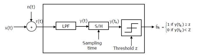
            Consider a baseband binary PAM receiver shown below. The additive channel noise n(t) is whit with power spectral density SN(f)=N0/2=10-20 W/Hz. The low-pass filter is ideal with unity gain and cutoff frequency 1MHz. Let Yk represent the random variable y(tk).
            Yk=Nk if transmitted bit bk=0
            Yk=a+Nk if transmitted bit bk=1
            Where Nk represents the noise sample value. The noise sample has a probability density function, PNk(n)=0.5ae-α|n| (This has mean zero and variance 2/a2). Assume transmitted bits to be equiprobable and threshold z is set to a/2=10-6V.


54.        The value of the parameter α (in V-1) is
            (A)        1010                  (B)        107                   (C)        1.414x10⁻¹⁰        (D)        2x10-20

55.        The probability of bit error is
            (A)        0.5xe-3.5            (B)        0.5xe-5              (C) 0.5xe-7                     (D)        0.5xe-10

                                                Q. No. 56 – 60 Carry One Mark Each

56.        Which of the following options is the closest in meaning to the world below: Circuitous
            (A)        Cyclic                (B)        indirect              (C)        confusing           (D)        crooked

57.        The question below consists of a pair of related of related words followed by four pairs of words. Select the pair that best expresses the relation in the original pair. Unemployed: Worker
            (A)        fallow : land                                          (B)        unaware : sleeper
            (C)        wit : jester                                            (D)        renovated : house

58.        Choose the most appropriate word from the options given below to complete the following sentence:
            If we manage to ________ our natural resources, we would leave a better planet for our children.
            (A)        uphold               (B)        restrain             (C)        Cherish                         (D)        conserve

59.        Choose the most appropriate word from the options given below to complete the following sentence:
            His rather casual remarks on politics _______ his lack of seriousness about the subject.
            (A)        masked             (B)        belied                (C)        cherish              (D)        conserve

60.        25 persons are in a room. 15 of them play hockey, 17 of them play football and 10 of them play both hockey and football. Then the number of persons playing neither hockey nor football is:
            (A)        2                      (B)        17                     (C)        13                     (D)        3

                                                            Q. No. 61 – 65 Carry Two Marks Each

61.        Modern warfare has changed from large scale clashes of armies to suppression of civilian populations. Chemical agents that do their work silently appear to be suited to such warfare; and regretfully, there exist people in military establishments who think that chemical agents are useful tools for their cause.
            which of the following statements best sums up the meaning of the above passage:
            (A)        Modern warfare has resulted in civil strife.
            (B)        Chemical agents are useful in modern warfare.
            (C)        Use of chemical agents in warfare would be undesirable.
            (D)        People in military establishments like to use chemical agents in war.

62.        If 137+276=435 how much is 731+672?
            (A)        534                   (B)        1403                 (C)        1623                 (D)        1513

63.        5 skilled workers can build a wall in 20 days; 8 semi-skilled worker can build a wall in 25days; 10 unskilled workers can build a wall in 30 days. If a team has 2 killed, 6 semi-skilled and 5 unskilled workers, how long will it take to build the wall?
            (A)        20 days             (B)        18 days             (C)        16 days             (D)        15 days

64.        Given digits 2,2,3,3,3,4,4,4,4 how many distinct 4 digit numbers greater than 3000 can be formed?
            (A)        50                     (B)        51                     (C)        52                     (D)        54

65.        Hari (H), Gita (G), Irfan (I) and Saira (S) are sibiligs (i.e. brothers and sisters). All were born on 1st January. The age difference between any two successive siblings (that is born one after another) is less than3 years. Given the following facts:
            i.          Hair’s age + Gita’s age > Irfan’s age + Saira’s age.
            ii.          The age difference between Gita and Saira is 1 year. However, Gita is not the oldest and Saira is not the youngest.
            iii.         There are not twins.
                        In what order were they born (0ldest first)?
            (A)        HSIG                (B)        SGHI                 (C)        IGSH                 (D)        IHSG